It is based on the McWire-design (http://reprap.org/wiki/McWire_Cartesian_Bot_1_2), but I have adapted it to whatever parts I could get hold of. I think I have been lucky to find very fine parts, and that they fit together remarkably well. The ingenious thing about this design is that it's very forgiving on sloppy workmanship, witch I have been relying on. I have built it in our living-room, but dirty and noisy work have I done in the shed where I have a small vice and a very cheep foldable workbench. I have used only simple tools, the only powertools I have used is a cordless drill/screwdriver (no drill stand), a random orbital sander and an angle grinder.
Structure
The structure is totally different from the original design. The U-shaped square pipes come from a coat-hanger i found in the attic... I added the 45 x 45 mm studs to make room for the X-axis motor, and with a couple of washers in between, I even could fit the PSU under the Y-axis. The PSU have I attached to the bottom board with double-sided adhesive tape. This tape is originally intended for laying carpet, but it's very versatile, I use it for many things. The back plane has two functions. It provides sideways stability and it's a perfect place to mount the electronics. I stole some beads from my kids to use as spacers under the electronics. They have a big box full, I don't think they will miss like 20 of them. The Y-stage is only clamped on the structure. That way I can adjust the tool both "x-wise" and "y-wise" if needed.


X- and Y-stages
The X- and Y-stages are basically the same as the original design, but the rails are some nice aluminum profiles I found in the metal recycle-bin at work. They are a bit shorter than I was aiming at in the beginning, however the belts are not longer either, so they match.
All board material are from a couple of laminate flooring I found in the attic. I could not find find any teflon sheets for the sliding bearings, at least with a price-tag I could accept. I'm hoping the floor-surface is somewhat wear-resistant, and that the friction will be acceptable low. If not, I could upgrade later. I was thinking of lubricating the rails with a very thin layer of some kind of lubricant on the rails, but I'm afraid it would attract dust and eventually have a grinding effect. I know there are dry lubricants, but I haven't tried it yet.
The stepper motors have I salvaged from two discarded braille embossers. I could not find any specs on them but they seem pretty strong and by comparing dimensions i am pretty sure they are Nema23. Two of the steppers had timing pulleys. I had a stroke of genius and instead of going through the hassle of removing them and get a very slow machine with threaded rod, i let them stay on and made a quite fast machine with belt driven x- and y-stages. I simply made a mounting plate for the motor and another on the other end with a support wheel. The wheel is simply a skate bearing on a M8 bolt.
I made belt guides out of a soda can, and made very thin washers, also out of the soda can and put between the bearing and the belt guides. This was to make a tiny gap between the rotating bearing and the stationary belt guide. This is probably over complicated, it would possibly have worked with just bigger washers.


Z-stage
The Z-stage is even closer to the McWire design. The circular hole in the aluminum profiles are threaded with M8 about 15 mm deep, how lucky can you be? Mounting the motor was just making a mounting plate and screwing it on.

I couldn't find enough springs, so on the vertical bearing arms, I use double rubber bands. They are easily replaceable, also the tension needs to be relatively low, otherwise the friction against the Z-rail gets to high.

The threaded rod is stainless steel M6. The pinion was pressed on really hard on the stepper motor, so instead of removing it, I locked two nuts against each other at the end of the threaded rod. I secured them with thread-lock and tightened them really hard. I used heat shrink tubing to attach the threaded rod to the motor. I hooked up the motor to the electronics and let it spin while i heated the tubing with a hot air gun I borrowed from my wife. The joint flexes a bit, but I think as long as the weight of the Z-stage is constant, I think it will work.
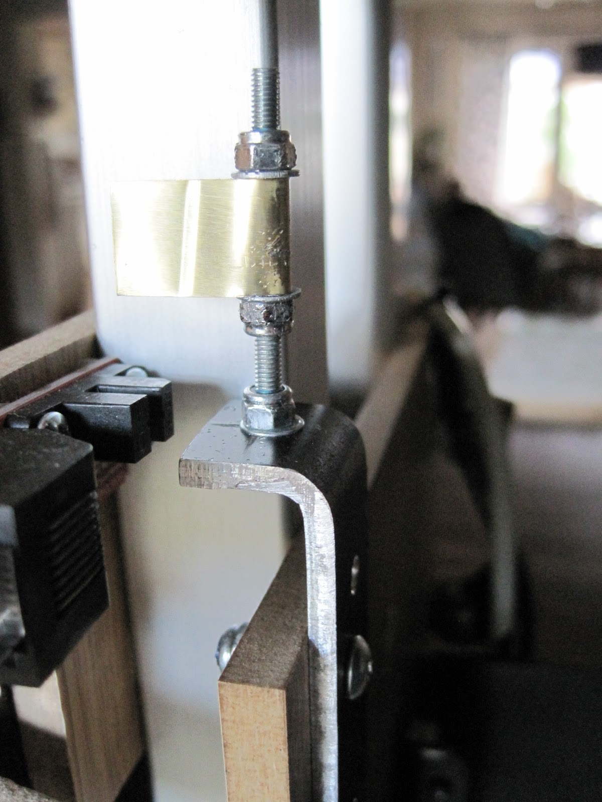
I wrapped the coupling nut with several layers of adhesive tape, and clamped it in a P-shaped pipe clamp. However that was not strong enough, my Z-stage is quite heavy, and dropped right onto the print-bed while I was printing. I have now made another variant that supports the nut, I hope it will work better. It's cut and bent out of a aluminium sheet. I think the pictures describes it better than words.


Electronics
I bought the Makerbot “generation 3 electronics mostly assembled” (http://store.makerbot.com/generation-3-electronics-mostly-assembled.html), but I changed to the Reprap firmware. Partly because I wanted to use the acceleration functionality to spare my belts, and partly, I was under the impression that Makerbot firmware did not work with a stepper-driven extruder, witch was what i was going to build. I am using Reprap software and firmware witch was brand new when it was time to test the printer (Reprap-2010-08-06).

Because I'm using a stepper extruder with the Reprap firmware, I soldered on a cable for the STEP and DIR signals from the motherboard to the extruder controller. It was a quick fix just to try it out, it's not pretty, but it works. Hopefully i will find time to make a nicer cable some day.
The H-bridges on the extruder controller get very hot, so I have cut a piece of a heat sink from an old graphics card and glued it on with thermal glue. I'm not sure if this is enough, so I'm trying to print a fan duct / holder for a 40 mm fan.

The power-supply is a standard 145 W ATX power-supply, I had laying around. I have not made any calculations, but I think it it is powerful enough. When I add a heated bed, I will most probably either have to exchange it for a more powerful one, or the heated bed must have its own power-supply.
Extruder
Two of the stepper motors had a pinion pressed on, I use this to grab the filament. It is a bit big, the diameter is about 11 mm, but the motor is quite strong, so that should not be a problem. I was worried about the resolution being to low, however with the 1 mm nozzle it is 0,78 mm extruded filament / step, and it seems to work. I realize that 0.5 mm nozzle will require a lot more torque, and the resolution will be way worse (3,11 mm / step). In time we'll see if it works anyway.


I made the no-lathe barrel & nozzle (http://blog.reprap.org/2009/05/no-lathe-barrel-nozzle.html) OK, I cheated on this one, I used a lathe to drill a 1mm hole trough a 5mm M4 set screw. Then I drilled up the socket to 3 mm, not sure if this is necessary though. Since I used insulated nichrome wire from makerbot, it was just wrapping it around the barrel and taping it with polyimide tape (same as Kapton tape). The tape have i bought incredibly cheap from Dealextreme. I have read that some people were not satisfied with their tape, but I haven't had any problem with it. This is the one rated 300 C (http://www.dealextreme.com/details.dx/sku.5101). I tried to get the nichrome as close to the tip as possible, so i taped on the thermistor above the nichrome. I'm not sure if this is is the best way to do it though. I insulated the thermistor leads by gently separating them and then bending them parallel and sandwich them between two pices of polyimide tape. i soldered the ends to the wires. I have read that nichrome is hard (impossible?) to solder, so I used the metal parts from a terminal block and finally wrapped them with polyimide tape.

For the first tests I just put a piece of the carpet-tape on the Y-stage. Now I have taped on a piece of 3 mm acrylic sheet I had laying around. In the picture above You can see how the extruder plowed a nice groove when the Z-stage dropped onto the print-bed. I will exchange or at least flip the acrylic sheet when I'm sure it won't happen again.
End-stops
The endstops are screwed on a piece of laminate flooring. The flags are pieces from an aluminium mackerel-can. It is a bit stiffer than from a soda can, but can still be cut with a pair of ordinary scissors. (Unless You are worried about the scissors will go dull.) The X- and Y-flags are just taped on the underside of the stages, there is no need to adjust them with any precision. The Z-flag is curled up to a pipe I have threaded onto the longest M3 screw I could find. The idea is that it can be adjusted with great precision thanks to the low pitch of the M3 thread. I'm using the RJ45 connectors, they are a bit bulky, but cat-5 cables are easy to find and very easy to plug in and out.

The future
My first priority is to make something similar to Nopheads "no compromise extruder" (http://hydraraptor.blogspot.com/2009/11/no-compromise-extruder.html). The current extruder jams VERY often. I'm quite convinced that the problem is heat that travels up the barrel and makes the filament bulge. I am also eager to get a 0.5 mm nozzle. With a smaller nozzle , there is a big chance I will be forced to change the drive mechanism to get enough torque and resolution.
I want to mount a fan on the extruder-controller to cool the H-bridge, I'm not sure that the heatsink is enough.
I also must make some kind of sane routing of all the cables. Now it looks like a nest of vipers. And a more serious cable for the STEP and DIR signals between the motherboard and extruder-controller.
Next I must experiment with the software and learn how to configure it to get god print quality.
Since I'm printing in our living-room, I want to do something about the fumes. It smells quite bad and I guess it's not very healthy. I'm thinking about putting the printer in some kind of box with a fan and a filter with activated carbon.
Then I will probably try to print myself a set of Mendel parts (or whatever is the current stable version at that time...)
Eventually I will probably try to build a heated bed.
Well, this was a very long post, extra credit to anyone who have read all the way down here! :-)
Let me know if you have a lot of issues out of your extruder, if you do I will send you a wades.
SvaraRaderaThanks for the nice offer, Niel! I will let You know how it turns out.
SvaraRaderaAluminium Cable Manufacturers – A renowned aluminium cable manufacturers in India and one of the leading aluminium cable suppliers in Delhi India.
SvaraRaderaAluminium Cable Manufacturers ? A renowned aluminium cable manufacturers in India and one of the leading aluminium cable suppliers in India.
SvaraRadera